RGB Led control
via bluetooth modules HC-05, HC-06
Hello, today i want to show you how can control RGB Led using Arduino, HC-05 or HC-06 module and Android.
In this project RGB Led can have three states, auto - depends on PIR sensor and manual control with on / off state.
Also you can control the color by setting the values for each color from 0 to 255.
We shall to look at the example of sketch where i show how can handle Serial input and control colors of the RGB Led.
And i'll explain how can use KvushCo Bluetooth Terminal, specifically how can set up sliders and buttons for achieve aim.
KvushCo Bluetooth Terminal Download app
Arduino sketch Download
Part 1. Arduino sketch.
First of all define constants, color mode, led state and setup our pins.
//define PWM pins for each color
#define RED           3
#define GREEN         5
#define BLUE          6

//colors value
int r, g, b;

//Possible operating states of the LED.
enum LedState {automatic, on, off};
enum ColorMode {set, process};

//and default value
LedState ledState = automatic;
ColorMode colorMode = set;

void setup() {
    Serial.begin(9600); //for HC-06 could be 38400
    pinMode(RED, OUTPUT);
    pinMode(GREEN, OUTPUT);
    pinMode(BLUE, OUTPUT);

    digitalWrite(RED, LOW);
    digitalWrite(GREEN, LOW);
    digitalWrite(BLUE, LOW);
}
Now look at the loop() function.
First, every time we start a new loop, we check the incoming Serial.
If there is input data, then further we divide the control into two logical paths.
First, if the current state is a color setting, then all incoming data is treated as color data.
Until a definite template (<int:int:int>) arrives, the color state does not change.
And second we receive other commands.
void loop() {
  if (Serial.available() > 0) {
    //all serial data is treated as color data until the colorMode is set
    if (colorMode == process) {
      Serial.println("-----------------------------");
      Serial.println("Waiting color data");
      setRGBcolor(&r, &g, &b, &colorMode);
    }
    //receive other BT commands
    else {
      switchCaseBTcommand();
    }
  }
}
Now time for look at setRGBcolor() function.
The function parse the incoming chars and save the integers into int r, g, b
'<' - is a data start character;
':' - is a delimiter character;
'>' - is a data end character.
void setRGBcolor(int *r, int *g, int *b, ColorMode *mode) {
  const byte numChars = 32;
  char receivedChars[numChars];
  char tempChars[numChars];        // temporary array for use when parsing
  static byte ndx = 0;
  char startMarker = '<';
  char endMarker = '>';
  char delimiter = ':';
  char rc;
  static bool recvInProgress = false;
  bool newData = false;

  //get newData
  while (Serial.available() > 0 && newData == false) {
    rc = Serial.read();
    if (recvInProgress == true) {
      if (rc != endMarker) {
        receivedChars[ndx] = rc;
        ndx++;
        if (ndx >= numChars) {
          ndx = numChars - 1;
        }
      } else {
        receivedChars[ndx] = '\0'; // terminate the string
        recvInProgress = false;
        ndx = 0;
        newData = true;
      }
    }
    else if (rc == startMarker) {
      recvInProgress = true;
    }
  }

  //parsing newData
  if (newData == true) {

    strcpy(tempChars, receivedChars);
    char *strtokIndx;

    strtokIndx = strtok(tempChars, delimiter);     // get the first part - the string
    *r = atoi(strtokIndx); // copy it to messageFromPC
    strtokIndx = strtok(NULL, delimiter); // this continues where the previous call left off
    *g = atoi(strtokIndx);     // convert this part to an integer
    strtokIndx = strtok(NULL, delimiter);
    *b = atoi(strtokIndx);     // convert this part to an integer

    newData = false; //new data was recived, reset flag
    *mode = set; //color was set, change color mode to set
  }
}
While writing this function, I was very helped by this subject,
Serial Input Basics - by Robin2 from forum.arduino.cc
Only i want to notice here that
Serial.parseInt()
Serial.parseFloat()
Serial.readBytes()
Serial.readBytesUntil()
All of these are blocking functions that prevent the Arduino from doing something else until they are satisfied, or until the timeout expires.
setRGBcolor() function do the same job without blocking.
Finally the simple function switchCaseBTcommand() which receive integer as command and changes states and modes.
Here I decided to use Serial.parseInt() as an easier way, even at the expense of speed. But here it is not so critical.
void switchCaseBTcommand() {
  int val = Serial.parseInt();
  //switch commands received through BT
  switch (val) {
    /* can be any commands defined as an integer,
     * here just example.
     * const int AUTO = 0; const int ON = 1; and so on
    */
    case AUTO:
      ledState = automatic;
      break;

    case ON:
      ledState = on;
      break;

    case OFF:
      ledState = off;
      break;

    case SET_COLOR:
      colorMode = process;
      break;
  }
}
Oops, just nearly forgot. In loop() function i did not add any code which will control RGB Led, so here it is.
//block of code controlling the LED
  switch (ledState) {
    case automatic:
      ledControl(RED, GREEN, BLUE, outDarkMotion);
      break;

    case on:
      ledControl(RED, GREEN, BLUE, true);
      break;

    case off:
      ledControl(RED, GREEN, BLUE, false);
      break;
  }
bool outDarkMotion this is simple flag which get true when PIR sensor registered any motion and an Light sensor registered a darkness.
So our loop() function now look like as below
void loop() {
  if (Serial.available() > 0) {
    //all serial data is treated as color data until the colorMode is set
    if (colorMode == process) {
      Serial.println("-----------------------------");
      Serial.println("Waiting color data");
      setRGBcolor(&r, &g, &b, &colorMode);
    }
    //receive other BT commands
    else {
      switchCaseBTcommand();
    }
  }
  //block of code controlling the LED
  switch (ledState) {
    case automatic:
      ledControl(RED, GREEN, BLUE, outDarkMotion);
      break;

    case on:
      ledControl(RED, GREEN, BLUE, true);
      break;

    case off:
      ledControl(RED, GREEN, BLUE, false);
      break;
  }
}
ledControl() is listed below
void ledControl(int red_pin, int green_pin, int blue_pin, bool ledPowerOn) {
  if (ledPowerOn == true) {
    analogWrite(red_pin, r);
    analogWrite(green_pin, g);
    analogWrite(blue_pin, b);
  } else {
    digitalWrite(red_pin, LOW);
    digitalWrite(green_pin, LOW);
    digitalWrite(blue_pin, LOW);
  }
}
Perhaps this is the whole sketch, so now move to Android part
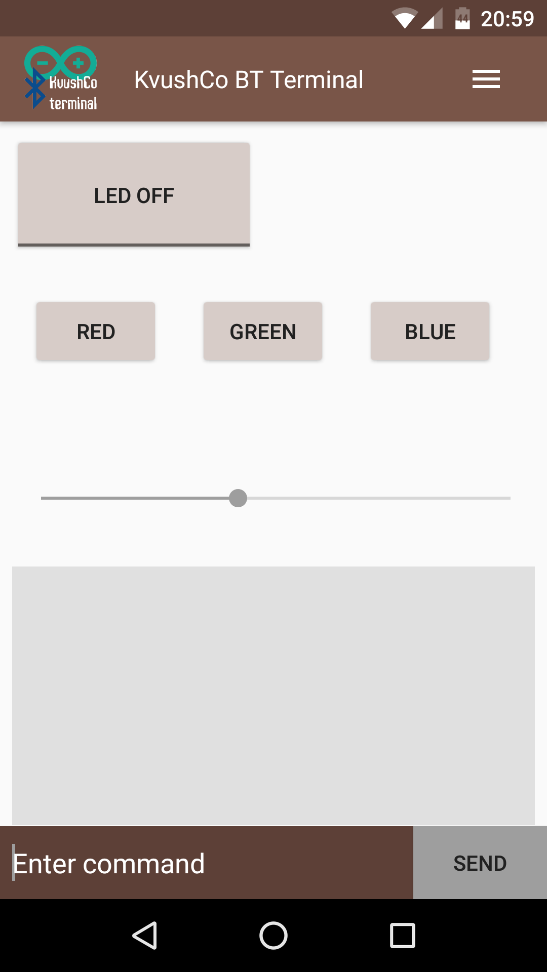
Part 2. Android, set up KvushCo Bluetooth Terminal
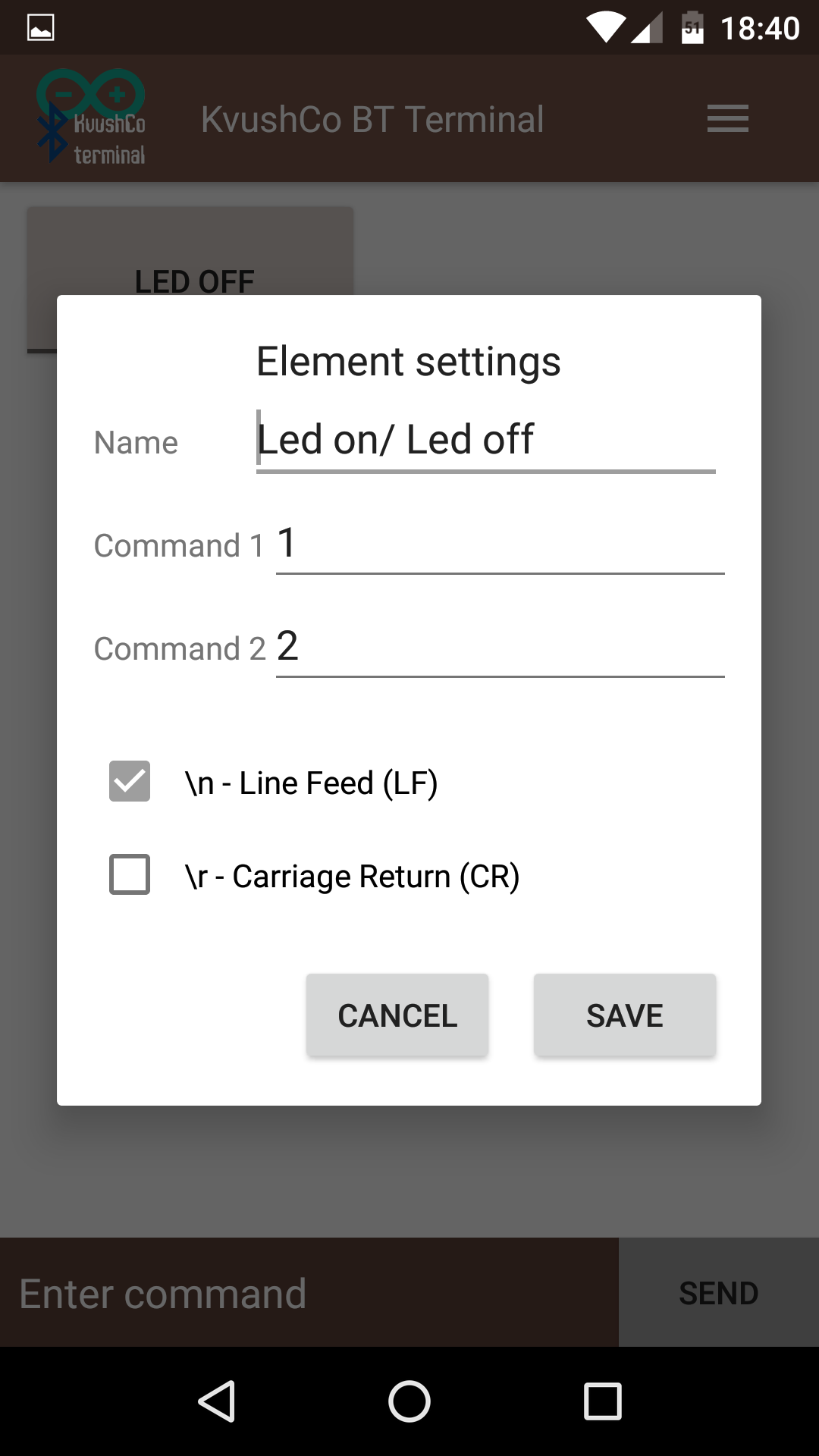
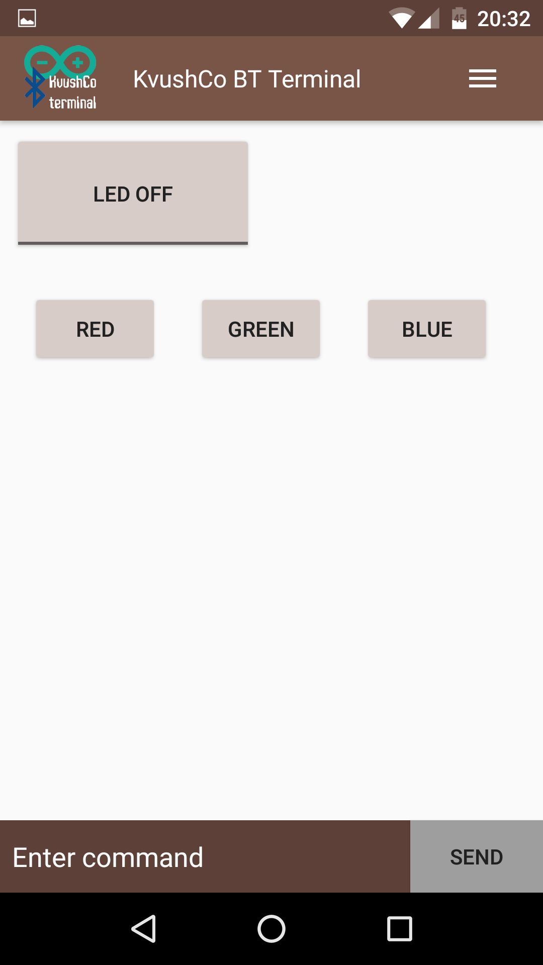
First add an toggle button, which will turn on the LED, give it name, and set up commands.
Toggle button have two state. Therefore in settings setup command 1 and command 2 for each state separately.
For example we assign the command 1 as "1", which corresponds to const ON in switchCaseBTcommand() and
command 2 as "2", which correponds to const OFF.

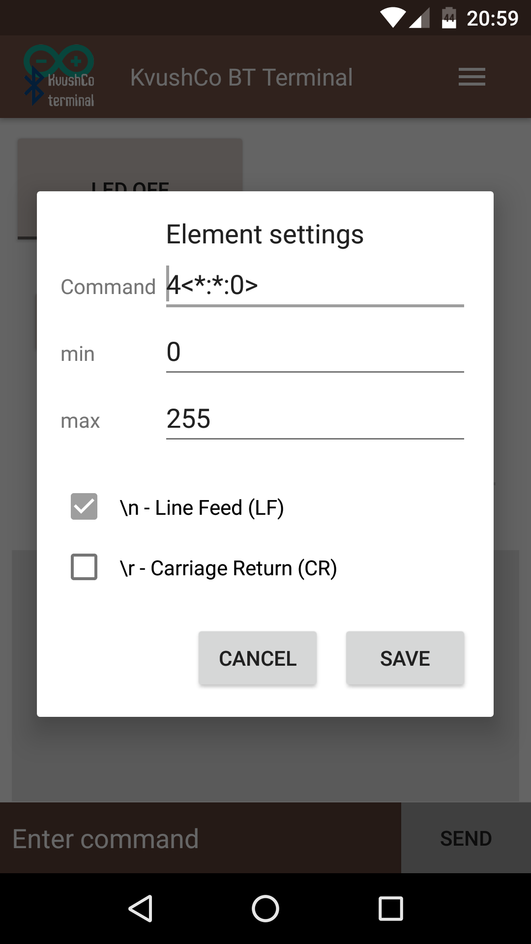
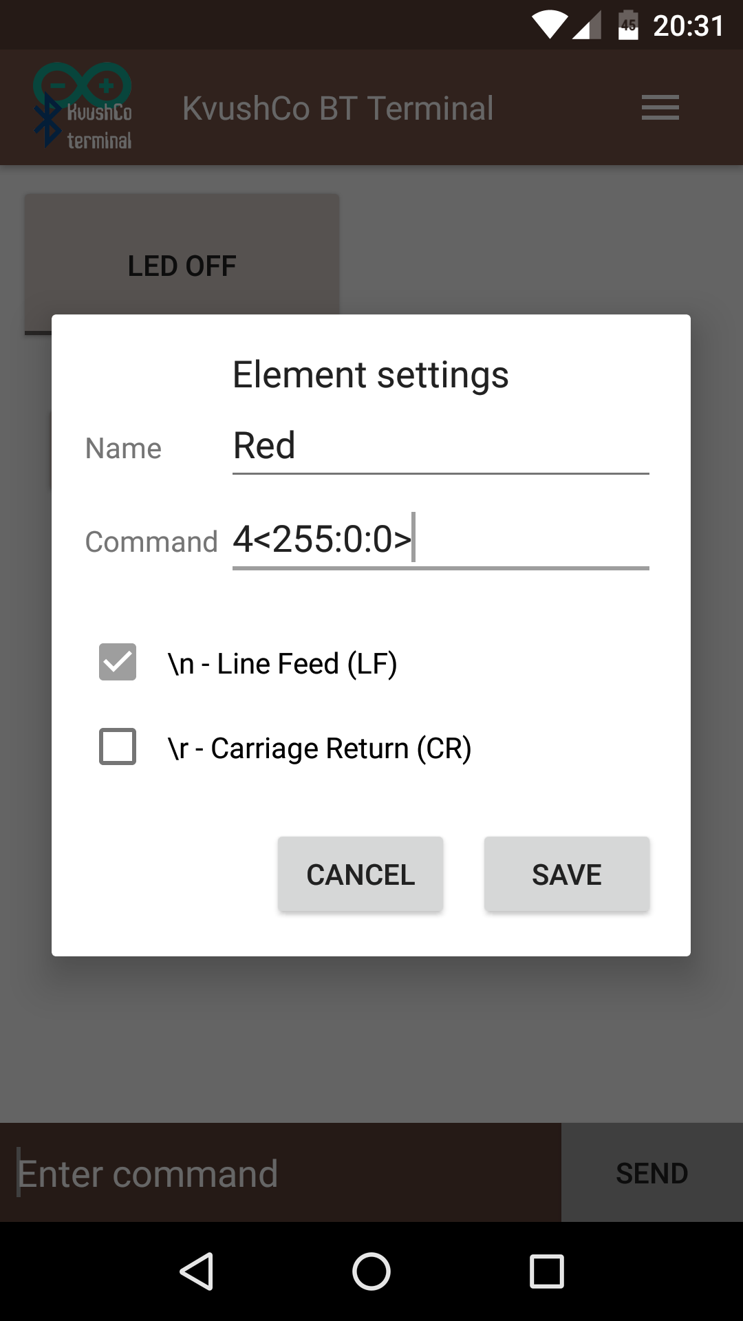
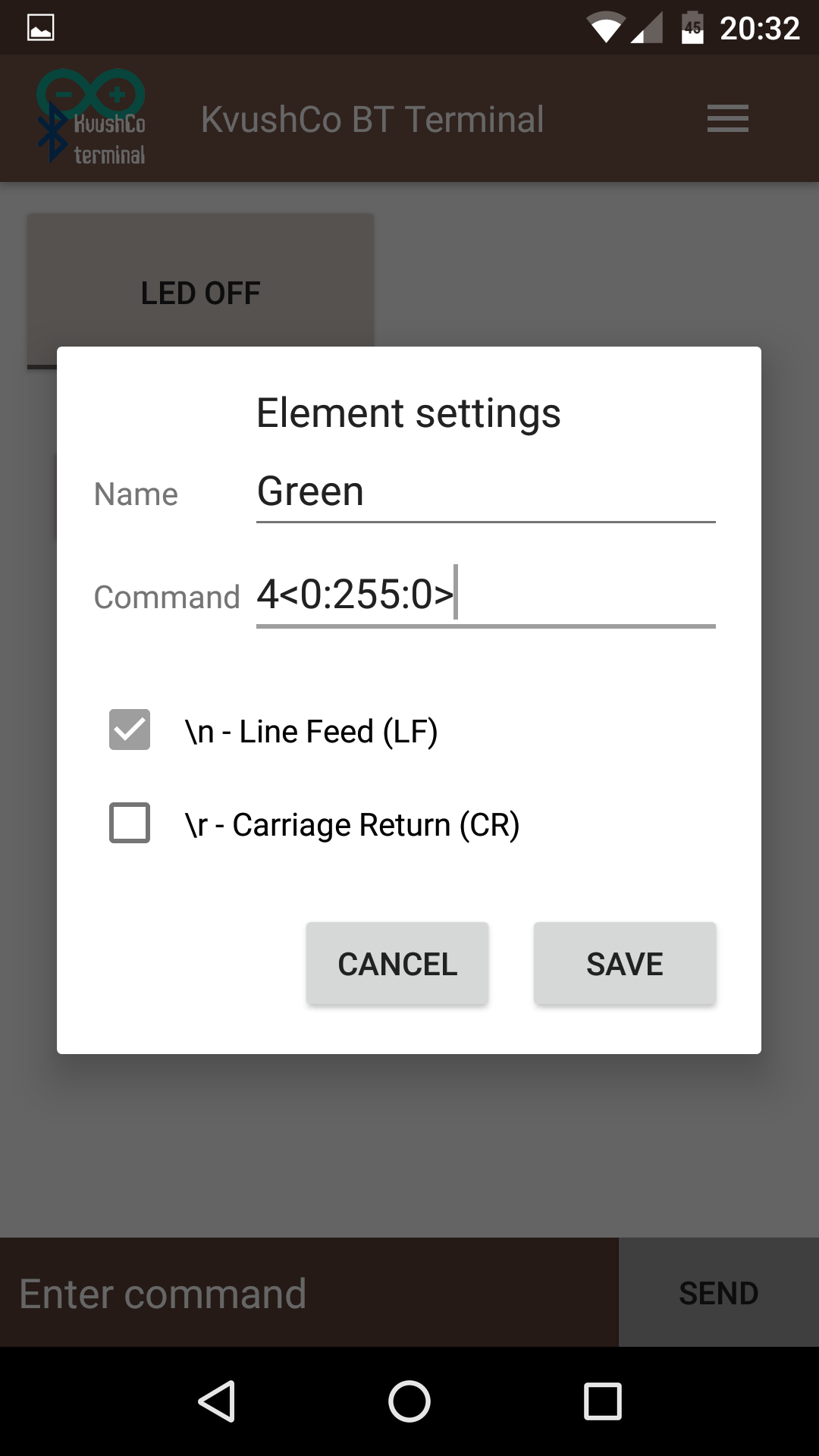
Now let's add some buttons with defined colors.
According to setRGBcolor() function, color should be setup with string "<int red: int green: int blue>"
But before send this string we should to set colorMode = process. To do this, add "4" before the string.
- Red color - "4<255: 0: 0>";
- Green color - "4<0: 255: 0>";
- Blue color - "4<0: 0: 255>";
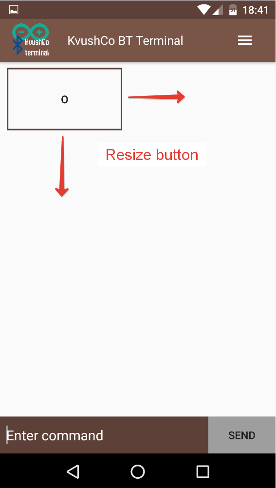
Finally let's add the slidebar. The slidebar is sending command during the move event. Thus, you can smoothly adjust the brightness of Led.
In the settings of the slider accepts three parameters.
The command must contain *. It will be replaced by a value from the slider. It can be any string with any number of *.
For example: R*; *G; <0:*:0>; <*:*:255>; etc. By default it is just *, this mean that slider will send integer between min and max.
Min and max accept only integer value.